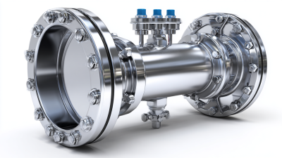
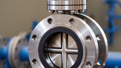
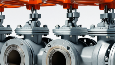
A triple offset butterfly valve is more than a compact alternative to a gate or ball valve. Its three-dimensional disc geometry reduces rubbing during operation, helping protect the sealing surfaces. That detail matters in high-temperature steam, refinery, power generation, and demanding process lines.
Valve engineer and author Philip L. Skousen emphasized a practical principle: “Reliable valve performance begins with matching the design to the service.” This idea supports the purpose of this guide. The top 10 types of triple offset butterfly valves should not be judged by appearance alone. Pressure class, body material, disc alloy, seat construction, actuation method, and fugitive-emission requirements can change the correct selection.
Some designs use metal seats for severe heat and fire-safe applications. Others include special coatings for corrosive fluids or abrasive particles. Lug, wafer, and double-flanged configurations also affect installation, maintenance, and pipeline loading. Small differences become expensive later.
Field experience teaches another lesson. A valve may pass a workshop test yet perform poorly after incorrect alignment, weak supports, or unsuitable gasket compression. That is easy to overlook.
Not every “triple offset” valve offers the same durability. Manufacturing tolerances, inspection records, pressure testing, and material traceability deserve careful review. Standards such as API 609, ISO 5211, and applicable fire-safe requirements provide useful benchmarks, but standards cannot replace engineering judgment.
This overview compares ten practical valve types, their operating strengths, limitations, and typical applications. The categories are useful, though not perfect. Actual service conditions must decide the final choice.
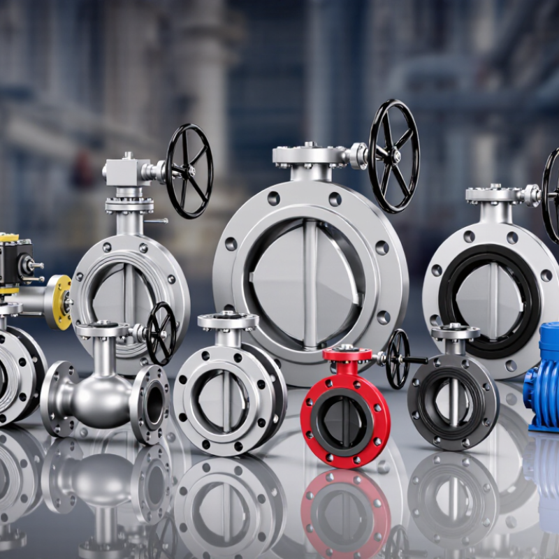
Top 10 Types of Triple Offset Butterfly Valves
Triple Offset Butterfly Valve Fundamentals and Operating Geometry
A triple offset butterfly valve uses three carefully controlled geometries. The first offset moves the stem behind the pipe centerline. The second shifts it away from the disc centerline. The third creates a conical sealing surface around the seat axis.
This geometry changes the opening motion. The disc lifts away from the seat almost immediately. It does not scrape continuously across the sealing surface. Less rubbing can reduce wear, operating torque, and particle generation during cycling. A properly selected metal seat can support demanding temperatures and pressures. However, performance still depends on materials, machining accuracy, and installation quality.
The valve body may use wafer, lug, double-flanged, or welded-end construction. Other versions support cryogenic, high-temperature, fire-safe, vacuum, or severe-service applications. These are service categories, not interchangeable designs. An experienced engineer checks pressure class, temperature range, media behavior, leakage requirements, and actuator torque before selection.
Small details matter. Pipe misalignment can load the disc unevenly. Incorrect flange spacing may damage the seat. A field inspection should confirm disc clearance and stem orientation. The geometry is powerful, but not foolproof. A drawing can look correct while real piping introduces stress. That deserves review.
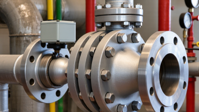
Triple offset butterfly valves use three geometric offsets: the shaft is positioned behind the disc sealing plane, displaced from the pipe centerline, and aligned with a conical seat axis. This geometry minimizes rubbing during rotation and creates a cam-like lift-off effect after the disc moves away from the seat. The chart shows commonly used ASME pressure classes and their nominal pressure ratings at approximately 100°F (38°C); actual valve ratings depend on body material, temperature, end connection, and applicable standards.
Triple offset butterfly valves are commonly classified by sealing design and seat configuration. The categories can overlap, which is easy to overlook. The ten practical types include metal-to-metal seated valves, laminated metal-graphite seated valves, solid metal seated valves, hard-faced seated valves, and graphite-backed fire-safe valves. These designs suit high temperatures, abrasive fluids, or demanding shutoff duties. In field inspections, seat finish often matters as much as the material itself. A small scratch can increase leakage.
The remaining types focus on seat arrangement and operating direction. Replaceable-seat valves simplify maintenance, while integral-seat valves reduce joint leakage. Bidirectional sealing valves support flow reversal, whereas pressure-assisted unidirectional seats use line pressure to improve tightness. Cryogenic extended-stem configurations protect the seat from extreme cold. High-cycle low-friction designs use carefully controlled contact geometry. That sounds simple. It is not.
Selection should match pressure class, temperature, fluid cleanliness, and expected cycling. Metal seats tolerate heat better than soft materials, but they require accurate machining and alignment. Laminated seats can improve resilience, yet their layers need careful inspection after service. A replaceable seat may lower downtime, although its fasteners and sealing surfaces add inspection points. Engineers should verify leakage class, flow direction, shaft loading, and fire-safe requirements before approval. Field experience helps, but it can also create bias. A familiar seat design is not automatically the safest choice.
Triple offset butterfly valves can be grouped by body, disc, and shaft construction. The body group contains four types: wafer, lug, double-flanged, and butt-welded valves. Wafer bodies fit between pipeline flanges and save space. Lug bodies allow separate pipe-side maintenance. Double-flanged bodies suit larger pipelines and demanding alignment conditions. Butt-welded bodies create a permanent connection, often used where leakage control is critical. Field experience shows that flange spacing can affect installation more than catalogue dimensions suggest.
The disc group includes three types: solid-disc, streamlined-disc, and laminated-disc valves. Solid discs offer strength in high-pressure service. Streamlined discs reduce flow disturbance and may lower pumping losses. Laminated discs can reduce weight, but their layered construction requires careful inspection. Small details matter. Disc edge finish directly affects sealing performance. A classification may look simple, yet temperature, pressure, and erosion can change the best choice.
The shaft group includes one-piece, two-piece, and through-shaft designs. One-piece shafts provide a direct load path and fewer internal joints. Two-piece shafts can improve assembly flexibility, though alignment deserves close attention. Through-shaft designs support heavy-duty torque transmission across the disc. During commissioning, technicians should check shaft runout, packing compression, and seat contact. I have seen valves selected correctly on paper but poorly matched to real operating cycles. That gap deserves honest review.
Triple offset butterfly valves are selected by service conditions, not appearance. Ten common configurations include carbon steel, stainless steel, duplex stainless steel, nickel alloy, cryogenic, high-temperature, high-pressure, pneumatic, electric, and manually actuated designs. Carbon steel suits many utility lines, while stainless steel resists corrosive fluids. Duplex materials offer stronger chloride resistance, but their welding quality demands careful control. Nickel alloys serve aggressive chemical and high-temperature applications. Material choice remains site-specific.
Pressure ratings must match both line pressure and temperature. Common designs follow ASME pressure classes such as 150, 300, 600, and 900, although actual limits vary with body material and temperature. The 2023 Global Valve Market report estimated industrial valve demand at more than USD 70 billion worldwide, reflecting broad use across energy, water, and process industries. That figure does not make selection easier. A valve rated Class 600 at ambient temperature may have a lower allowable pressure near 400°C.
Actuation changes operating speed and risk. Pneumatic actuators provide fast quarter-turn movement and suit emergency shutdown systems. Electric actuators support remote control, but cable routing and torque margins need attention. Hydraulic units deliver high torque for large valves. Manual gear operators remain practical where power is unavailable. According to the International Energy Agency’s 2023 energy infrastructure analysis, aging industrial assets require stronger reliability planning. Field experience shows a small mistake in actuator sizing can leave a valve moving slowly, or not moving at all. A tidy specification sheet can mislead. Temperature, cycling frequency, sealing torque, and maintenance access should be checked together.
Top 10 Types of Triple Offset Butterfly Valves: Selection Criteria for Industrial Service Applications
Triple offset butterfly valves are selected by service conditions, not appearance. Common configurations include wafer, lug, double-flanged, and butt-welded designs. Other categories cover cryogenic, high-temperature, fire-safe, fugitive-emission, jacketed, and subsea applications. Each type changes installation, inspection, or maintenance requirements. Start with the process medium. Abrasive slurry, dry gas, oxygen-rich service, and corrosive chemicals demand different body and sealing materials. Check compatibility carefully.
Pressure and temperature ratings must match real operating conditions, including start-up and emergency events. Do not rely only on normal line pressure. A metal seat can handle severe heat, but its performance depends on correct alignment and surface finish. Leakage classification also matters. Low-emission packing may be essential near toxic or volatile media. For large pipelines, flange rating, valve weight, actuator torque, and available space deserve early review. Small oversights become expensive.
Think about operation in the field. Electric, pneumatic, and hydraulic actuators suit different control systems and failure positions. A fire-safe design may support refinery isolation, while a cryogenic design needs extended bonnets and suitable materials. Verify applicable pressure, fire, emissions, and material standards with qualified engineers. Site testing is valuable. Yet test results can mislead when media temperature differs from factory conditions. I have seen selection sheets overlook cycling frequency, which later accelerated seat wear. A neat specification is not always a complete one.
| No. | Valve Type | Typical Seat and Trim | Typical Pressure Range | Typical Temperature Range | Suitable Industrial Service | Key Selection Criteria | Relevant Standards |
|---|---|---|---|---|---|---|---|
| 1 | General-Purpose Metal-Seated Triple Offset Valve | Metal-to-metal laminated or solid metal seat; stainless or nickel-alloy trim options. | Commonly ASME Class 150–600; higher classes are available in specialized designs. | Approximately −29°C to 400°C, depending on materials and packing. | Water, steam, air, hydrocarbons, process gases, and general chemical services. | Select body material, pressure class, end connection, shutoff rating, and actuator torque based on line conditions. | API 609; ASME B16.34; ISO 5208 |
| 2 | Wafer-Pattern Triple Offset Valve | Metal seat with a compact body installed between mating pipe flanges. | Typically ASME Class 150–300. | Approximately −29°C to 300°C, subject to seat and packing selection. | Utilities, cooling water, HVAC, low-to-moderate pressure process lines, and space-limited installations. | Confirm flange compatibility, bolt length, valve centering, line support, and allowable installation orientation. | API 609; ASME B16.5; ISO 5752 |
| 3 | Lug-Pattern Triple Offset Valve | Metal seat with threaded or tapped lugs allowing independent flange bolting. | Typically ASME Class 150–600. | Approximately −29°C to 400°C, depending on construction. | Dead-end service, tank isolation, maintenance sections, and systems requiring a mechanically stable connection. | Check whether the design is rated for dead-end service and verify downstream pressure limits during maintenance. | API 609; ASME B16.34; MSS SP-67 |
| 4 | Double-Flanged High-Pressure Triple Offset Valve | Robust metal seat, pressure-retaining body, and bolted or welded construction for high-load applications. | Commonly ASME Class 300–1500, depending on diameter and design. | Approximately −29°C to 400°C. | Pipeline transmission, power generation, refinery process units, and high-pressure gas or liquid systems. | Evaluate pressure-temperature rating, flange facing, shell test pressure, actuator thrust, and structural loads. | ASME B16.34; ASME B16.5; API 609 |
| 5 | Fire-Safe Triple Offset Butterfly Valve | Metal seat and graphite packing or gasket system designed to maintain isolation after soft components are exposed to fire. | Commonly ASME Class 150–600. | Usually −29°C to 400°C in normal operation; fire-test exposure is a separate qualification condition. | Refining, petrochemical, oil and gas, fuel handling, and other flammable-fluid services. | Require certified fire testing, antistatic continuity, emergency shutdown compatibility, and appropriate fugitive-emission control. | API 607; API 6FA; ISO 10497 |
| 6 | High-Temperature Triple Offset Valve | Heat-resistant metal seat, graphite packing, and alloy trim selected for thermal cycling. | Typically ASME Class 150–600. | Approximately 300°C to 650°C for suitably engineered materials; exact limits are design-specific. | Superheated steam, hot gas, thermal oil, exhaust gas, and high-temperature process lines. | Check thermal expansion, oxidation resistance, packing temperature limit, cycling frequency, and actuator sizing at temperature. | ASME B16.34; API 609; ISO 15848-1 |
| 7 | Cryogenic Triple Offset Butterfly Valve with Extended Bonnet | Cryogenic metal seat, low-temperature body and trim, extended bonnet, and controlled stem heat leak. | Commonly ASME Class 150–600. | Approximately −196°C to −29°C, depending on materials and qualification. | Liquefied nitrogen, oxygen, natural gas, argon, hydrogen, and other low-temperature fluids. | Verify low-temperature impact properties, bonnet length, seat leakage at cryogenic temperature, insulation clearance, and cleanliness requirements. | BS 6364; API 6D; ISO 28921-1 |
| 8 | Sour-Service Triple Offset Butterfly Valve | Materials and hardness levels controlled to resist sulfide stress cracking and hydrogen-related damage. | Commonly ASME Class 150–600. | Often approximately −29°C to 200°C, subject to material qualification and process chemistry. | Wet hydrogen sulfide, sour gas, sour crude, gas processing, and selected petrochemical services. | Define H₂S partial pressure, water content, chlorides, hardness limits, material traceability, and sour-service documentation. | NACE MR0175 / ISO 15156; API 609 |
| 9 | Oxygen-Clean Triple Offset Butterfly Valve | Compatible metal seat and trim with hydrocarbon-free cleaning, degreasing, and controlled packaging. | Commonly ASME Class 150–600. | Approximately −29°C to 200°C for many oxygen systems; oxygen compatibility must be evaluated for the actual pressure and temperature. | Industrial oxygen, medical-gas infrastructure, oxygen enrichment, and clean gas systems. | Confirm oxygen compatibility, ignition-risk controls, non-sparking materials, cleaning acceptance criteria, and contamination prevention. | ASTM G93; CGA G-4.1; EIGA 33/18 |
| 10 | Low-Emission Triple Offset Butterfly Valve | Metal seat with stem sealing designed and tested to limit fugitive emissions; graphite or advanced packing systems are common. | Commonly ASME Class 150–600. | Approximately −29°C to 400°C, depending on packing and emission qualification. | Volatile organic compounds, toxic gases, refinery service, chemical processing, and environmentally regulated facilities. | Specify leakage target, test temperature, cycling requirements, packing material, stem finish, and maintenance accessibility. | ISO 15848-1; API 624; API 641 |
Note: Pressure and temperature values are typical selection ranges rather than universal limits. Final valve selection must be verified against the manufacturer’s pressure-temperature chart, fluid composition, leakage class, applicable piping code, actuator requirements, and site-specific safety standards.
© Shipham Valves 2025. All Rights Reserved.
Website By PS Website Design Ltd
Request a Quote/Further Information
Download
We use cookies on this website, by continuing to browse the site you are agreeing to our use of cookies. Find out more.