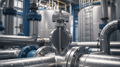
What Is a Lugged Butterfly Valve and How Does It Work?
Across water, HVAC, and process piping, a compact valve can carry a significant operational burden. The U.S. Environmental Protection Agency’s 2023 Drinking Water Infrastructure Needs Survey and Assessment estimates $625 billion in drinking-water investment needs over 20 years. That estimate is not a valve-market forecast. It does, however, show the scale of infrastructure where reliable isolation and maintainability matter. Small details count.
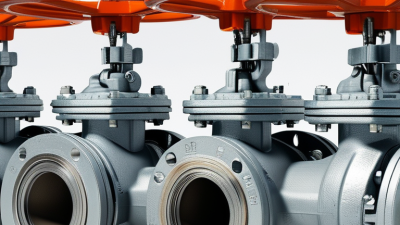
A lugged butterfly valve controls flow with a disc mounted on a stem. A quarter-turn rotates the disc from open to closed, while the seat helps form a seal. Threaded lugs around the body allow bolts to connect the valve to pipe flanges. This design can support end-of-line service, but only when the specific valve is rated for that condition and pressure. The distinction is easy to overlook.
API Standard 609 covers lug- and wafer-type butterfly valves, offering a useful technical reference for understanding their design and application. This guide explains the valve’s parts, operating action, common uses, and selection considerations. It also compares lugged designs with wafer-style valves, where installation and maintenance needs may differ. No single design fits every line. Pressure, temperature, fluid compatibility, and manufacturer limits all deserve careful review. That practical check is sometimes missed, even in otherwise sound specifications.
What a Lugged Butterfly Valve Is
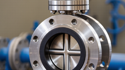
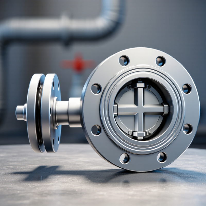
A lugged butterfly valve is a quarter-turn valve whose body has raised lugs with threaded holes around its perimeter. Bolts pass through each pipe flange and thread into the lugs, securing the valve without spanning both flanges. Inside, a circular disc sits across the flow path and turns on a stem. At a quarter turn, the disc moves from open to closed. Simple to picture. Unlike a wafer-style body, the lugged body has its own threaded connection points.
That distinction can seem minor until a line needs service. The design may allow one side of a pipeline to be removed while the valve remains bolted to the other side. Still, this is suitable only when the valve is rated for dead-end service and the installation follows its pressure limits. For example, a crew may isolate a pump line, remove downstream piping, and leave the valve attached upstream. Check the flow direction, seat material, and flange-bolt pattern against the system specification. Small details matter. An incorrectly selected seat can wear early, while uneven bolt tightening may distort the body or cause leakage. Lugged valves do not suit every fluid, temperature, or end-of-line condition; review the data sheet and site conditions carefully.
What Is a Lugged Butterfly Valve and How Does It Work?
A lugged butterfly valve has threaded lugs around its body for bolting between pipe flanges. Turning the stem rotates the disc through a quarter-turn to open, close, or partially restrict the flow. Depending on its design and pressure rating, a lugged valve may also be suitable for dead-end service.
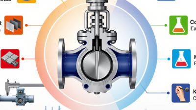
The chart shows typical disc angles, not flow percentages. Actual flow at intermediate positions depends on the valve design and operating conditions.
Key Components and Their Functions
A lugged butterfly valve uses a circular body with threaded lugs around its perimeter. Bolts pass through the pipe flanges and engage these lugs, so each pipe side can be disconnected independently. That can help during maintenance on dead-end lines, but only when the valve is rated for that service. The body carries the load. It does not, by itself, guarantee safe isolation.
Inside, the disc rotates about a quarter-turn to regulate or stop flow. A stem connects the disc to a lever or actuator; the seat forms the sealing surface between disc and body. Seat material affects chemical compatibility, temperature limits, and shutoff performance. Small part. Big effect.
API Standard 609, 9th edition (2021), covers lug-type butterfly valve design, pressure-temperature ratings, inspection, and testing. Its published rating tables are more useful than assuming one pressure limit fits every valve.
ISO 5211:2017 specifies actuator attachment interfaces, helping match an actuator to the valve. Check the actual torque requirements, too. A common oversight is selecting the actuator from pipe size alone; disc loading and operating conditions matter.
The details can be less tidy than the catalog suggests.
How the Lugged Connection Secures the Valve
A lugged butterfly valve has threaded lugs cast or formed around its body. Bolts pass through the holes in each pipe flange and screw into these lugs. The valve is held between the flanges, but each side has its own set of bolts. No long bolts need to span the entire assembly. A close fit matters.
This connection can make maintenance more controlled. If the downstream pipe section must be removed, the valve may remain bolted to the upstream flange. That is only safe when the valve is rated for dead-end service at the expected pressure. The rating varies by design; never assume every lugged valve can hold pressure from one side alone. Check the valve documentation and the installation conditions.
During installation, align the valve body with the pipe and keep the disc slightly open if the manufacturer recommends it. Tighten flange bolts evenly, using the specified pattern and torque. Uneven tightening can distort the body or affect disc movement. Check that the disc clears the pipe bore through a full turn. One small oversight: a valve can look centered while its disc still catches a nearby liner or pipe edge. Don’t rely on appearance alone.
What Is a Lugged Butterfly Valve and How Does It Work? — How the Lugged Connection Secures the Valve
| Feature |
How It Works |
Why It Matters |
| Valve body and lugs |
The valve body has projecting lugs around its perimeter. Many designs have threaded holes in these lugs to receive bolts. |
The lugs provide individual bolting points for securing the valve between two pipe flanges. |
| Lugged connection |
Bolts pass through the flange holes and engage the threaded lugs on the valve body. The exact bolt arrangement depends on the valve and flange design. |
The valve can be attached to each side separately, rather than relying only on long through-bolts that span both flanges. |
| Opening and closing |
Turning the stem rotates the disc, typically through about 90 degrees. The disc is aligned with the flow path when open and turned across the flow path when closed. |
This quarter-turn action allows the valve to control or shut off flow quickly. The valve is not necessarily intended for precise throttling in every application. |
| Sealing |
When closed, the disc presses against a seat inside the valve body. Seat material and construction vary by valve design. |
Leakage performance depends on the selected valve, seat, service conditions, and applicable test requirements. |
| Pipe alignment |
The valve is installed between compatible flanges, with the body centered and the bolting tightened according to the manufacturer’s instructions. |
Correct flange alignment and tightening help prevent damage to the valve, seat, or piping connection. |
| End-of-line service |
Some lugged butterfly valves are designed to remain bolted to one flange when the downstream pipe or flange is removed. |
One-sided, or dead-end, service is not suitable for every lugged valve. Confirm the valve’s rating and installation instructions before using it this way. |
| Pressure and temperature limits |
Allowable operating limits depend on the valve’s materials, size, seat, design, and applicable standards. |
Check the valve’s documented pressure-temperature rating against the actual operating conditions; lugged construction alone does not define a rating. |
| Typical applications |
Butterfly valves are used in many water, HVAC, and industrial piping systems where the selected materials and ratings are suitable. |
Confirm fluid compatibility, required shutoff performance, and service conditions before selecting a valve. |
Note: Lug patterns, bolting requirements, pressure ratings, and dead-end capabilities vary by valve design. Always follow the valve and piping system specifications.
How the Disc Controls Flow
Inside a lugged butterfly valve, the disc turns on a shaft across the pipe. At about a quarter-turn, it moves from closed to open. When closed, the disc’s edge presses against the seat and blocks flow. As it turns, a curved gap forms around the disc, letting fluid pass. The opening grows, but flow does not rise in a perfectly straight line. Pressure, fluid viscosity, and valve geometry all affect the result.
At the halfway point, the disc still obstructs much of the bore. Near fully open, it sits edge-on to the stream, though it still creates some resistance. That detail matters.
The U.S. Department of Energy’s Improving Pumping System Performance: A Sourcebook for Industry reports that pumping can account for 25–50% of energy use in some industrial operations. A poorly chosen throttling point may add avoidable system losses.
The disc angle alone cannot predict the exact flow; check the valve’s flow-coefficient data and the system pressure. Real piping is less tidy than a diagram. The same setting can behave differently after installation.
Common Applications and Selection Factors
Lugged butterfly valves are common in water-treatment plants, wastewater lines, HVAC loops, and industrial process piping. Threaded lugs around the valve body accept bolts from each flange. This lets crews remove downstream piping while keeping the valve attached upstream, when its design rating permits. The disc turns a quarter-turn to control flow. It is compact and quick to operate. But it is not automatically suitable for every throttling duty.
Infrastructure reports show why water service deserves careful attention.
The U.S. EPA’s 2023 Drinking Water Infrastructure Needs Survey estimates $625 billion in needs over 20 years. Its 2022 Clean Watersheds Needs Survey estimates $630.1 billion for wastewater infrastructure. These figures describe infrastructure needs, not valve sales. Still, they underline the importance of durable, maintainable equipment in water systems.
Check the fluid, solids content, pressure, temperature, and corrosion risk before selecting a valve. Match the seat and disc materials to the actual service, not just the pipe size. For isolation, confirm the required dead-end pressure rating; lugged designs vary.
Review actuator clearance, too. A tight pump-room wall can make an otherwise suitable valve awkward to service. That detail is easy to miss.