How to Choose the Right Wafer Butterfly Valve?

Choosing the right wafer butterfly valve starts with the job it must perform, not just the pipe size. A valve on a cooling-water line faces different demands from one handling abrasive slurry or frequent temperature changes. Pressure, temperature, fluid compatibility, flow rate, and operating frequency all shape the choice. Small details matter. A disc that suits clean water may wear quickly in a gritty process.

Valve engineer and author John V. Ballun’s work offers a useful selection principle, paraphrased here: “Match the valve to the service, not merely to the line size.” This is a guide, not a verified verbatim quotation. That distinction matters when technical advice is presented as a direct quote.

This guide explains how to compare body materials, disc and seat options, pressure ratings, and actuation methods. It also considers installation space, flange compatibility, and maintenance access. Check the manufacturer’s pressure-temperature data against your actual operating conditions; a nominal rating alone can mislead. Not always. A compact wafer design can save space between flanges, but it still needs correct alignment and suitable fasteners. Look closely at the fluid and the duty cycle. A valve that opens only during scheduled maintenance is not the same as one cycling dozens of times each hour. Selection can feel straightforward on a catalog page. In the plant, it is less tidy. One overlooked detail can change the result. The aim is a dependable fit, not simply the lowest price or the shortest lead time.
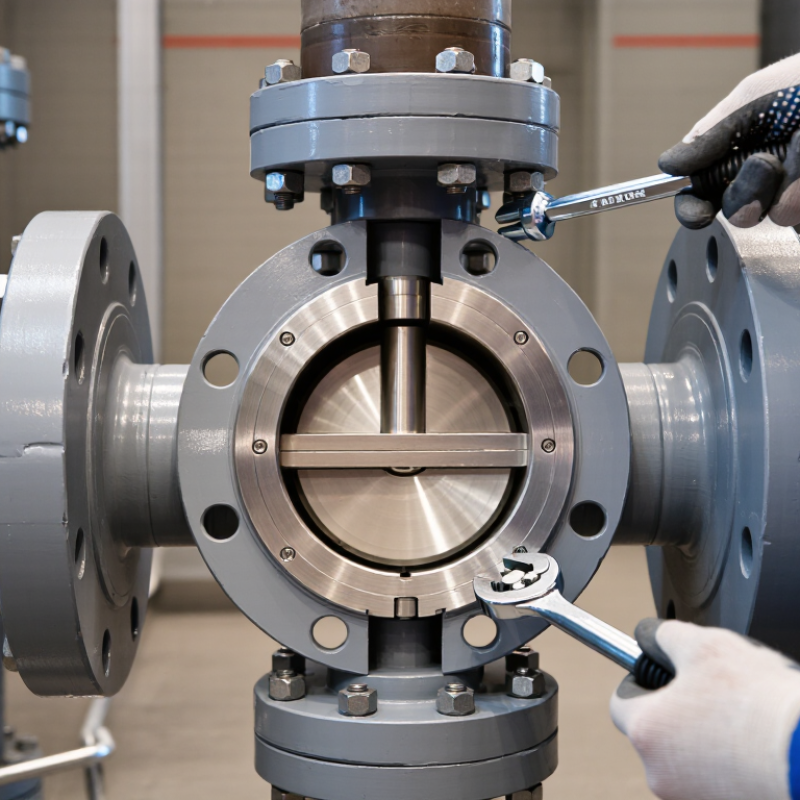
How to Choose the Right Wafer Butterfly Valve?

Define Fluid, Pressure, and Temperature Limits Using ASME B16.34 Ratings

Start with the fluid, not the valve size. Water, steam, oils, and mildly corrosive chemicals place different demands on the body, disc, seat, and stem. Check chemical compatibility for every wetted material, including seals. A fluid that looks harmless may still swell an elastomer or cause corrosion over time.

Use the valve’s specified ASME B16.34 pressure-temperature rating as a selection limit, not a guess. Confirm the pressure class and material group, then read the allowable pressure at your operating temperature. The maximum rating can decrease as temperature rises. Also check whether the wafer valve is designed and documented to the standard; not every product uses the same rating basis. A rating alone does not establish suitability.

Be specific. Record normal and maximum pressure, temperature during startup, and any pressure surges. Include vacuum or pressure differences across a closed disc where relevant. Compare these conditions with the valve body rating and the separate limits for its seat and other components. The weakest limit governs. Leave a practical margin, and confirm the final selection with the valve documentation or a qualified engineer. Real systems fluctuate; that detail is easy to underestimate.

Compare Concentric, Double-Offset, and Triple-Offset Disc Designs

A wafer butterfly valve’s disc geometry affects sealing, torque, wear, and service life. Concentric designs place the stem and disc centrally, pressing a resilient seat around the disc edge. They suit water, HVAC, and other moderate-duty services where compact installation matters. They are often economical. But elastomer limits on temperature and chemical compatibility can narrow the operating window.

Double-offset designs move the stem away from the disc center and seat plane. This reduces rubbing as the disc opens, making them a practical choice for higher pressure, temperature, or cycling demands. Triple-offset designs add a conical sealing geometry, so the disc lifts away from the seat with little sliding contact. Metal seats can handle tougher thermal conditions, but installation alignment and actuator sizing deserve careful checks. Small details matter.

For selection, compare actual pressure, temperature, media, cycle frequency, and required shutoff performance—not design labels alone. API 609 classifies butterfly-valve design categories, while ISO 5208:2015 sets pressure-test and leakage-acceptance criteria. These references help define measurable requirements; they do not promise identical performance in every installation. EPA’s Protocol for Equipment Leak Emission Estimates also treats valves as a distinct component class in emissions estimates, a reminder that sealing and maintenance matter in service. A seat that looks robust on paper may still be wrong for abrasive solids or an incompatible fluid.

Select Seat and Disc Materials for Media Compatibility and ISO 5208 Leakage Rates

How to Choose the Right Wafer Butterfly Valve?

Select the seat and disc for the actual fluid, not just its name. EPDM often suits water service, while NBR may work better with oils. PTFE handles many chemicals, but concentration and temperature still matter. Check the manufacturer’s compatibility data against the fluid’s full operating range. A neat material chart is not enough. I have seen overlooked cleaning chemicals change the selection.

The disc faces the process directly. Stainless steel may suit many clean or mildly corrosive services; duplex stainless steel can offer greater resistance in some chloride environments. Coated ductile iron may be economical, but coating damage can expose the substrate. Consider solids, velocity, temperature, and cycling. The AMPP/NACE IMPACT study estimated corrosion costs at about 3.4% of global GDP, showing why material choices deserve careful review. That figure covers broad economic impacts, not valve failures alone.

Specify the required seat leakage rate under ISO 5208:2015, rather than asking only for a “tight shutoff.” The standard defines leakage-rate categories and test procedures; acceptance depends on the selected rate, test medium, and valve configuration. Rate A means no visually detectable leakage during the specified test. Confirm that the tested assembly matches the chosen seat, disc, pressure, and direction of flow. Ask for the test report. Check the details. A laboratory result may not perfectly reflect worn seats, temperature swings, or installation conditions.

How to Choose the Right Wafer Butterfly Valve?

Select seat and disc materials for media compatibility and ISO 5208 leakage requirements.

The ranges shown are indicative for common material grades; actual limits depend on the compound, valve design, pressure, and service conditions. Check chemical compatibility for the specific medium. ISO 5208 leakage acceptance depends on the specified leakage rate and test conditions; Rate A means no visually detectable leakage during the test.

Verify Wafer Dimensions and Pressure Class Against API 609 Requirements

API 609 is a useful starting point, but nominal pipe size alone cannot confirm a wafer valve will fit. Check the valve category and specified edition, then compare its face-to-face length, body diameter, and bolt-hole clearances with the mating flanges. A few millimeters can matter. Confirm that the body sits within the flange bolt circle and that the disc clears the pipe bore when fully open. A common field mistake is checking the face-to-face dimension while overlooking disc clearance or liner thickness.

Pressure class needs the same careful review. A Class 150 marking does not mean the valve is rated for 150 psi in every condition. Confirm the pressure-temperature rating for the valve’s materials, then compare it with the flange class and the system’s maximum operating pressure and temperature. The seat and end connection can also limit service conditions. Use dimensioned, certified drawings and check the exact project specification against the applicable API 609 edition. A datasheet may look complete and still leave one detail unclear; resolve that before ordering.

Size the 90° Actuator by Torque, Cv/Kv, and ISO 5211 Mounting Standards

How to Choose the Right Wafer Butterfly Valve?

A wafer butterfly valve turns through 90 degrees, but actuator sizing is not a simple diameter match. Estimate required torque at the valve’s actual differential pressure, fluid conditions, and operating temperature. Check breakaway, running, and seating torque values against the valve supplier’s data. Then select an actuator whose output covers the highest relevant torque, with an appropriate service margin. Too little torque can leave the disc partly open. Too much may stress the stem or disc. Do not size by guesswork.

Cv or Kv helps confirm flow capacity, not actuator torque. Use the required flow rate and allowable pressure drop to check whether the valve can pass the process flow. A valve that meets the flow target may still need a different actuator. ISO 5211 specifies the actuator mounting interface; verify the flange pattern, shaft connection, and coupling dimensions before ordering. The standard helps parts fit, but it does not confirm the actuator’s torque is sufficient. It is easy to overlook that distinction.

Tips: Ask for torque data at your operating pressure, and check the full 90-degree travel. Recheck assumptions when conditions vary. A small mismatch can matter.

How to Choose the Right Wafer Butterfly Valve? - Size the 90° Actuator by Torque, Cv/Kv, and ISO 5211 Mounting Standards
Selection Step What to Check Practical Guide or Example Why It Matters
1. Confirm valve size and service Nominal pipe size, pressure class, fluid, temperature, flow direction, and operating conditions. For example, a DN100 (NPS 4) valve should match the pipeline, mating flanges, and applicable pressure and temperature limits. Nominal size alone does not establish the valve’s flow capacity, pressure rating, or suitability for the fluid.
2. Calculate required flow capacity Use the design flow rate, fluid specific gravity, and pressure drop across the valve. For liquids in US units: Cv = Q × √(SG / ΔP), where Q is in US gpm and ΔP is in psi. For metric units: Kv = Q × √(SG / ΔP), where Q is in m³/h and ΔP is in bar. These equations estimate the required flow coefficient at the stated operating point. Gas and steam flow require separate compressible-flow calculations.
3. Compare Cv and Kv data Check the valve’s published coefficient at the intended opening and compare it with the required value. For water at 500 US gpm with a 4 psi valve pressure drop, the estimated requirement is Cv = 250. The equivalent is approximately Kv = 216, using Cv ≈ 1.156 × Kv. Cv and Kv depend on valve design, diameter, and opening angle. A valve’s full-open coefficient does not by itself confirm good control at partially open positions.
4. Obtain valve torque data Request the valve manufacturer’s torque values for the actual size, seat material, differential pressure, fluid, and temperature. Review breakaway, running, seating, and any relevant end-of-travel torque values. Use the worst applicable value for actuator selection. Butterfly-valve torque varies with design and service conditions; it should not be inferred from nominal diameter alone.
5. Apply a suitable sizing margin Account for service severity, uncertainty, cycling frequency, and the actuator’s output at its minimum available supply pressure. If the specified valve torque is 120 N·m and the agreed sizing factor is 1.5, the actuator should provide at least 180 N·m at the relevant operating point. A sizing factor is an engineering choice, not a universal value. Excessive actuator torque can damage the valve or seat; confirm allowable torque limits.
6. Match the 90° actuator Confirm the actuator’s quarter-turn travel, output torque curve, supply type, control mode, and fail action if required. For spring-return or other fail-safe service, check available torque throughout the full stroke in both the powered and spring-driven directions. Actuator torque can vary through the stroke and with air pressure, electrical supply, or spring position. Select from the manufacturer’s output data.
7. Verify ISO 5211 mounting Check the valve top flange, actuator mounting interface, bolt pattern, locating features, and stem or drive dimensions. Specify the required ISO 5211 interface and confirm that the actuator and valve interfaces match; use a correctly designed bracket or coupling if needed. ISO 5211 defines mounting-interface dimensions. Matching the interface designation alone does not verify drive engagement, alignment, or torque capacity.
8. Check the complete assembly Verify valve pressure and temperature limits, flange compatibility, actuator enclosure or ingress protection, and accessory requirements. Review solenoid valves, position indicators, limit switches, positioners, and manual overrides where the application requires them. The assembled valve and actuator must meet the process, installation, and control requirements—not just the nominal size or mounting standard.

Note: Flow and torque examples are illustrative calculations, not product ratings. Confirm final valve coefficients, torque requirements, allowable stem torque, and ISO 5211 interface dimensions with the applicable equipment data and project specifications.

Request a Quote/Further Information

    Download