Call us on: +44 (0) 1482 323163
Request a Quote
Choosing the right gas valves is not merely a catalog exercise; it is a safety and reliability decision. Each valve must suit the system’s pressure, temperature, gas composition, and operating cycle. A valve installed on a cold outdoor line may face different demands from one controlling hot process gas indoors. Small details matter. Seal materials, body alloys, connection types, and actuator choices can all affect performance. A polished datasheet helps, but it cannot reveal every weakness in an installation.
The International Energy Agency’s Global Methane Tracker 2024 estimates that fossil fuel operations released about 120 million tonnes of methane in 2023. This figure does not attribute emissions to valves alone. It does, however, underscore why leak prevention, inspection, and sound equipment selection deserve attention. Even a technically suitable valve can underperform if it is poorly installed or maintained.
A dependable selection process starts with the service conditions, not a preferred product name. Define the gas, pressure range, temperature extremes, required shutoff performance, and expected cycling. Then check compatibility with applicable codes and project specifications. For pipeline service, API Specification 6D and ISO 14313 offer relevant design and testing frameworks; other applications may require different standards. Consider actuation and fail-safe requirements too. What should happen during a power loss? That question is easy to postpone—and risky to overlook. The sections ahead examine these factors so project teams can compare options with evidence, involve qualified engineers, and select gas valves suited to real operating conditions.
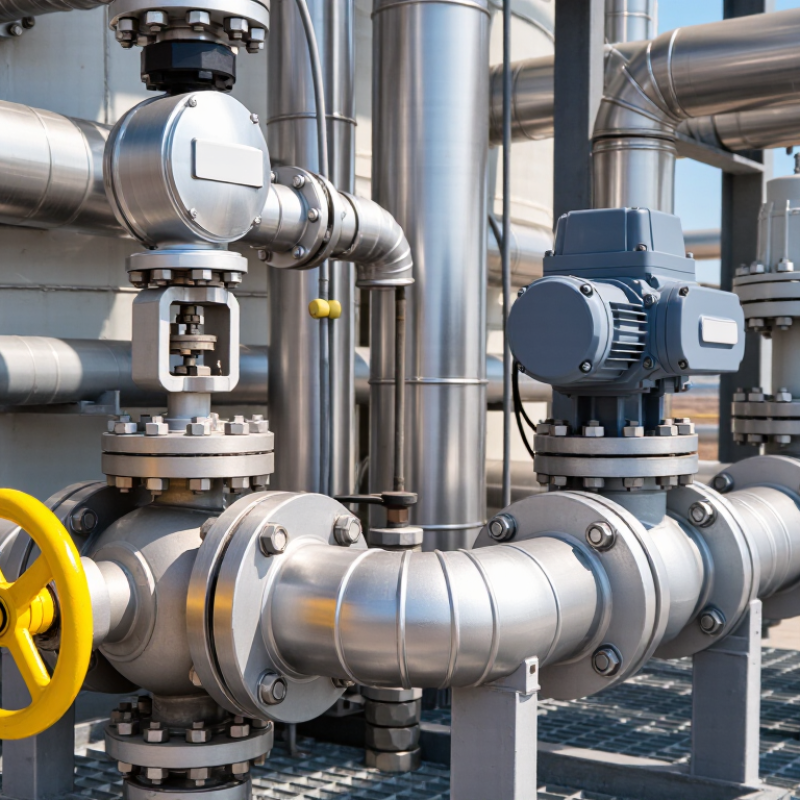
A gas valve should be selected by the job it must perform, not by its name alone. It may shut off supply, regulate pressure, or control flow to a burner. These functions are different. A manual isolation valve, for example, is not a substitute for a pressure-control device. Define the valve’s role at each point in the system, including what should happen during normal operation and when power or control signals fail. That distinction matters.
Map the valve’s location and operating conditions before comparing options. Check the gas type, inlet pressure range, required flow, temperature, connection size, and how often the valve will cycle. A valve serving an appliance may need a different response time than one used for routine isolation. Picture the installation: a valve tucked behind a cabinet may be hard to reach, while a vibrating pipe can stress a poorly supported connection. Small details matter. Review the manufacturer’s technical data and have a qualified professional confirm compatibility with the system design. It is easy to focus on flow capacity and overlook access for inspection; that is worth reconsidering before the layout is fixed.
| Project Application | Valve’s Primary Role | Common Valve Function | Key Selection Considerations | Important Project Checks |
|---|---|---|---|---|
| Residential gas appliance connection | Isolate the gas supply to an individual appliance for servicing or emergency shutoff. | Manual on/off isolation, commonly provided by a shutoff valve. | Gas type, connection size, pressure rating, installation location, and compatibility with the appliance and piping. | Confirm local code requirements, accessibility, approved installation methods, and leak testing procedures. |
| Boiler or furnace fuel train | Control and isolate fuel supplied to the burner as part of the combustion system. | Automatic safety shutoff; a separate control valve may regulate fuel flow where required by the system design. | Required flow capacity, inlet pressure range, operating voltage for actuated valves, response requirements, and burner compatibility. | Check the appliance design and applicable combustion-safety standards. Safety shutoff components should be selected and installed as a coordinated system. |
| Industrial burner or process heater | Provide the specified fuel-flow control and shutoff functions for the burner or heating process. | Modulating control, safety shutoff, or both, depending on the control and safety design. | Operating pressure, required flow range, control signal, valve response, gas composition, temperature, and pressure drop. | Verify the burner manufacturer’s requirements, safety interlocks, and the applicable industrial standards and regulations. |
| Gas pressure reduction station | Reduce a higher upstream pressure to a suitable downstream operating pressure. | Pressure regulation using a regulator; shutoff or relief devices may be specified separately. | Inlet and outlet pressure ranges, flow capacity, gas type, expected demand variation, and regulator droop. | Assess overpressure protection, venting requirements, installation orientation, and the downstream equipment’s pressure limits. |
| Gas distribution branch or equipment inlet | Stop flow in one direction or isolate a section of piping, as required by the system layout. | Check valves prevent reverse flow; isolation valves allow a section or item of equipment to be shut off. | Whether reverse flow is possible, permitted flow direction, pressure loss, materials, connection type, and service conditions. | Use a check valve only where the system design calls for backflow prevention; it does not replace an isolation or safety shutoff valve. |
| Gas system requiring overpressure protection | Limit pressure rise or relieve excess pressure to protect downstream equipment, where the design requires it. | Pressure relief or pressure-limiting function, selected for the system’s protection strategy. | Set pressure, relieving capacity, discharge arrangement, gas properties, and the pressure limits of protected equipment. | Relief devices require engineered sizing and a safe discharge arrangement in accordance with applicable codes and standards. |
Selection note: Define whether the project needs isolation, pressure regulation, flow control, reverse-flow prevention, or overpressure protection before choosing a valve. Final selection and installation should be verified against the system design, local regulations, and qualified gas-safety requirements.

© Shipham Valves 2025. All Rights Reserved.
Website By PS Website Design Ltd
Request a Quote/Further Information
Download