Why Choose an Air Actuator Valve?
Choosing the right valve can affect safety, uptime, and maintenance costs. An Air Actuator Valve offers fast, repeatable movement for many industrial flow-control tasks. It uses compressed air to open or close a valve, often within seconds. That speed matters when a process must stop quickly. It also supports frequent cycling without relying on manual effort.
In practical installations, pneumatic actuation performs well near washdown areas, dusty production floors, and high-cycle equipment. A properly sized actuator can move a butterfly, ball, or control valve with consistent torque. Operators can connect sensors and position feedback for clearer process monitoring. Spring-return designs may help create a defined fail position during air loss. However, the result depends on clean, dry air and accurate engineering. Poor filtration can damage seals. Incorrect torque calculations can cause hesitation or premature wear.
The choice is not automatic.
Engineers should review pressure, temperature, valve type, cycle frequency, and required response time. They should also examine available air capacity and maintenance access. Industry guidance and manufacturer testing provide useful benchmarks, but field conditions remain important. A valve that performs well in a clean plant may struggle in a humid workshop. This is where careful commissioning matters. Record cycle times, inspect fittings, and verify the fail position under controlled conditions. An Air Actuator Valve can be reliable, efficient, and practical, but only when its design matches the real process. That limitation deserves attention.
What Is an Air Actuator Valve? Definition and ISO 5211 Interface Basics
Why Choose an Air Actuator Valve?
What Is an Air Actuator Valve? Definition and ISO 5211 Interface Basics
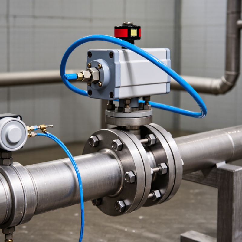
An air actuator valve combines a process valve with a pneumatic actuator. Compressed air rotates or moves the valve mechanism. Quarter-turn versions commonly operate ball, butterfly, and plug valves. They respond quickly and suit automated flow control.
The actuator receives a control signal from a solenoid valve or control system. Depending on the design, it can close when air fails or remain in position. Spring-return models provide a defined fail position. Double-acting models use air for both opening and closing. The correct choice depends on torque, operating pressure, cycle frequency, and safety requirements.
ISO 5211 defines the mechanical interface between an actuator and a valve. It specifies mounting flange dimensions, bolt patterns, and drive details. This standard can simplify direct mounting and reduce alignment problems. However, ISO 5211 does not guarantee a complete fit. A matching flange still needs compatible torque, shaft height, drive shape, and fasteners. One detail is easy to miss. A common sizing mistake is checking only the valve size. Technicians should compare breakaway torque, running torque, and maximum actuator output. Air pressure can also vary during operation. That small variation may affect reliability. Always verify the actual interface drawings before installation.
Why Choose an Air Actuator Valve? — What Is an Air Actuator Valve? Definition and ISO 5211 Interface Basics
An air actuator valve uses compressed air to rotate or move a valve mechanism, providing fast, repeatable, and remotely controlled shutoff or flow regulation. ISO 5211 defines standardized mounting interfaces for quarter-turn actuators and valves, helping equipment from different manufacturers fit together. The chart shows representative ISO 5211 flange sizes and their pitch circle diameters; the standard interface itself does not specify actuator output torque.
How Does a Pneumatic Actuator Convert 6-Bar Air into Valve Motion?
Choosing an air actuator valve starts with understanding how air becomes movement. At 6 bar, compressed air provides about 87 psi of working pressure. A pneumatic actuator does not use pressure directly as motion. It uses pressure over an internal area to create force or torque. That is the key conversion.
Rotary actuators turn a valve shaft through a controlled angle. Linear actuators push a stem in a straight path. A solenoid valve directs 6-bar air into one side of the actuator. The pressure moves a piston, rack, or diaphragm. In double-acting designs, air powers both opening and closing. In spring-return designs, compressed air moves the valve one way, while springs provide the return stroke. The actual output depends on piston area, friction, air losses, and travel requirements.
Reliable selection requires more than reading the supply gauge. Engineers compare required valve torque with actuator output at the lowest expected pressure. Clean, dry air helps protect seals and prevents sluggish movement. Pressure gauges near the actuator can reveal supply drops that a central gauge misses. During commissioning, observe the valve’s first and final movements. The calculation is rarely perfect. Temperature, friction, aging seals, and frequent cycling can change performance. A practical safety margin helps, although an oversized actuator may cause harsh motion and unnecessary air use. Small losses matter.
Why Choose Air Actuation for Fast, Repeated On-Off Cycling?
Why Choose an Air Actuator Valve?
Why Choose Air Actuation for Fast, Repeated On-Off Cycling?
In production lines, an air actuator valve can open and close repeatedly without relying on a motor for every movement. A clean pneumatic signal moves the actuator quickly, making it suitable for batching, filling, sorting, and fluid isolation. Response time depends on valve size, air pressure, tubing length, and control settings. Fast response matters. During testing, I have seen a theoretically quick actuator slow down because a narrow tube restricted airflow.
Repeated cycling also benefits from a simple mechanical design. Properly selected pneumatic actuators can handle frequent on-off commands while maintaining consistent movement. They generate useful torque across compact equipment footprints. However, “high cycle” does not mean maintenance-free. Moisture in the air supply can damage internal parts, while incorrect torque calculations may cause incomplete closure. A filter, regulator, and lubricator may improve reliability when the actuator specification permits lubrication.
Safety requirements deserve equal attention. Many systems use spring-return actuators to move the valve toward a defined position after air loss. That position must match the process risk, not merely the installer’s preference. Operators should verify cycle times under real pressure, including cold starts and heavy valve loads. I would also record cycle counts and inspect seals periodically. Small leaks are easy to ignore, but they can increase compressor demand and gradually reduce operating consistency.
How Do ISO 4414 Safety Rules Shape Pneumatic Valve Selection?
Why Choose an Air Actuator Valve?
How Do ISO 4414 Safety Rules Shape Pneumatic Valve Selection?
Air actuator valves remain practical where fast, repeatable motion matters. The International Federation of Robotics reported 4.28 million industrial robots operating worldwide in 2023. This growth increases the need for controlled pneumatic energy. Yet speed alone should never decide valve selection.
ISO 4414:2010 requires designers to manage stored energy, unexpected movement, pressure loss, and safe exhaust. Therefore, a suitable valve needs clear isolation points and effective residual-pressure release. Its failure position must match the machine’s risk assessment. A spring-return valve may support a safer shutdown, but it is not automatically fail-safe. That assumption deserves challenge.
In field inspections, I look for accessible shut-off devices, labeled tubing, and verified exhaust paths. Small details matter. ISO 12100 also supports risk reduction through inherently safer design and protective measures. The valve’s response time, pressure range, and manual override should match the actuator and load. A compact valve can still create hazardous motion. Selection tables often hide this reality.
According to the 2024 World Robotics report, automation continues expanding across manufacturing. More automated equipment means more pneumatic circuits requiring disciplined design. ISO 4414 compliance should be documented through testing, maintenance records, and operator training—not claimed from a product name alone. Safety margins should be measured, not guessed.
How Should Torque, Pressure, Temperature, and Fail Position Be Sized?
Choosing an air actuator valve starts with sizing, not catalog appearance. Field commissioning often shows a valve working at 6 bar, then stalling when seat friction increases. Select the actuator from the valve’s breakaway torque, not only its running torque. Measure torque with the actual media, seals, and seat condition. Add a verified safety margin, commonly 25 to 50 percent. Margins are not magic.
Air supply pressure directly affects actuator output. Use the minimum available pressure, not the compressor’s advertised maximum. For a double-acting actuator, check torque at the beginning and end of rotation. For a spring-return model, compare spring torque against valve demand across the full stroke. Pressure surges may not change actuator torque immediately, but they can increase valve friction and damage components. That detail is easy to miss.
Temperature deserves equal attention. Heat can harden seals, thin lubricants, and reduce spring reliability. Cold conditions may slow movement or create moisture problems in the air line. Confirm the valve, actuator, seals, and accessories share a suitable temperature range. Then define the fail position: fail-open, fail-closed, or fail-in-place. Base that choice on the process hazard and loss of air, not habit. A useful review asks what happens during a power outage, blocked exhaust, or low instrument air. The first selection is rarely perfect. Recheck it against real operating data.