What Are the Top Single Gauge Manifold Types?
Selecting the right Single Gauge Manifold is a practical decision, not merely a catalog comparison. These compact assemblies connect pressure instruments, isolate process lines, and simplify calibration work. In oil and gas, chemical processing, power generation, and water treatment, small design choices can affect safety, maintenance time, and measurement quality.
Industry data shows why this topic deserves careful attention. Grand View Research identifies continued growth in industrial valves and process-control equipment, driven by infrastructure upgrades and automation. MarketsandMarkets also reports expanding demand for pressure instrumentation across energy and manufacturing applications. These reports do not measure manifold sales directly, but they reveal a clear trend: reliable pressure-control components remain essential in modern plants. NIST guidance on measurement uncertainty further reminds engineers that accurate instruments depend on the complete measurement system, not the gauge alone.
The top manifold types usually include block-and-bleed, two-valve, three-valve, and five-valve designs. Each serves a different pressure-measurement arrangement. A two-valve manifold may suit basic isolation and calibration. A three-valve model supports differential-pressure transmitters. Five-valve configurations provide additional equalizing and venting functions for demanding service.
The choice matters.
Material compatibility, pressure rating, temperature limits, connection style, and installation space must be checked together. ASME B40.100 and relevant manufacturer specifications offer useful technical reference points. Still, no shortlist is perfect. A highly featured manifold may increase cost, weight, and operator confusion. A simpler model may be easier to maintain, but less flexible. This guide compares the leading Single Gauge Manifold types through performance, application fit, reliability, and practical installation experience.
Definition and Core Functions of Single Gauge Manifolds
What Are the Top Single Gauge Manifold Types?
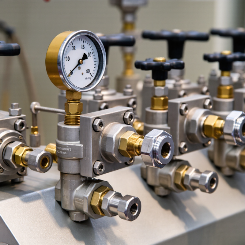
A single gauge manifold is a compact fluid-control assembly for one pressure instrument. It connects the process line to a gauge through controlled passages. Its core functions include isolation, pressure release, and safe gauge removal. In field service, this design can reduce tubing, leakage points, and installation time. A technician may close the process valve, vent trapped pressure, and inspect the gauge without disturbing the whole system. Small details matter here.
Common types include two-valve, three-valve, and five-valve configurations. A two-valve manifold usually provides process isolation and gauge venting. It suits straightforward pressure measurement. A three-valve version may add a test or calibration path. This arrangement helps technicians compare readings with a reference instrument. Five-valve designs offer more control for calibration, equalizing, and differential applications. They can be useful, but extra valves also increase cost and possible maintenance errors.
Selection should match pressure range, fluid compatibility, temperature, and connection standards. Stainless steel construction often supports demanding industrial environments, but material choice still requires engineering review. Thread quality and seal condition deserve close inspection. Over-tightening can damage fittings. That mistake is common. Correct valve sequencing also protects the gauge from sudden pressure changes. In practice, installation drawings and site procedures should guide every step. A manifold may look simple, yet poor venting can leave trapped pressure inside. That risk should never be assumed away.
Primary Types of Single Gauge Manifolds
Single gauge manifolds connect one pressure gauge to a controlled process line. Their primary types differ by valve count and operating purpose. The two-valve manifold uses one isolation valve and one vent valve. It suits ordinary pressure measurement and routine gauge replacement. Two valves. Simple, but limited.
The three-valve manifold adds a second isolation path or equalizing function. It supports safer checking when pressure conditions may vary. The five-valve version adds dedicated high-side, low-side, equalizing, and venting controls. It is more common where technicians need calibration access or differential-pressure verification. In field work, valve count should follow the maintenance plan, not appearance. More valves can improve control, yet they also create extra leak points and more operator decisions.
Industry reports show why selection matters. The International Energy Agency’s World Energy Investment 2024 estimated global energy investment near 3 trillion dollars, with clean-energy investment exceeding 2 trillion dollars. These projects require dependable measurement across compact process systems. A 2024 process-instrumentation market analysis also identified oil, gas, chemical processing, and power generation as major demand sectors. However, public market reports rarely separate single gauge manifolds by exact valve configuration. That limitation deserves attention. Procurement teams should verify pressure rating, material compatibility, temperature range, port geometry, and applicable requirements under ASME B16.34 and ISO 5208. A stainless-steel body may resist corrosion, but it cannot correct poor installation. Small details matter: thread sealant, tubing alignment, and accessible valve handles often determine real service reliability.
How to Compare and Select the Right Manifold Type
Choosing a single gauge manifold starts with the measurement task, not the valve count. A two-valve manifold usually provides isolation and venting for one pressure gauge. A three-valve design adds another isolation path or equalizing function. It can help during calibration, but it may add leak points and installation space. For differential pressure service, a five-valve arrangement is often more practical, with separate block, equalizing, and venting functions. The best choice depends on pressure range, process temperature, fluid compatibility, connection size, and maintenance access. The pressure sensor market is projected to grow from about USD 17.2 billion in 2023 to USD 29.2 billion by 2032, according to Fortune Business Insights’ 2024 market report. More instruments mean more attention to compact, reliable connections.
Tips: Match wetted materials with the process fluid. Check the pressure rating at operating temperature, not room temperature. Confirm whether the gauge needs calibration without disturbing the process. Standards such as ASME B40.100 and ISO 5208 can support gauge performance and leakage decisions. In field work, I have seen oversized manifolds selected because they looked safer. They were not always easier to operate. A smaller two-valve unit may suit a clean, stable line, while corrosive or pulsating service may justify a more complex design. Thread choice also matters. NPT, BSP, and tube connections are not automatically interchangeable. Recheck the datasheet, especially when space is tight. That step is easy to skip.
What Are the Top Single Gauge Manifold Types?
Two-valve manifolds typically provide one isolation valve and one bleed valve for basic pressure-gauge service. Three-valve manifolds add an equalizing valve and are commonly used with differential-pressure instruments. Five-valve manifolds add dedicated high- and low-side bleed or test functions, making them suitable for calibration, troubleshooting, and more complex measurement applications. The exact arrangement can vary by installation and process requirements.
Common Applications and Maintenance Considerations
Single gauge manifolds usually fall into three practical types: two-valve, three-valve, and five-valve designs. A two-valve manifold provides isolation and venting for basic pressure measurement. It suits pumps, filters, and compact hydraulic lines. A three-valve manifold adds an equalizing path. Technicians use it with differential-pressure instruments, especially across flow meters and filters. Five-valve versions add separate high- and low-pressure vents. They support calibration, troubleshooting, and safer instrument removal.
Application determines the better choice. Process skids often need three-valve manifolds for stable differential readings. Test benches benefit from five-valve layouts because technicians can connect calibration equipment without dismantling tubing. In my field observations, blocked impulse lines cause more confusion than failed gauges. Small details matter. Keep ports capped, tubing supported, and valve handles clearly identified.
The U.S. Department of Energy’s Operations & Maintenance Best Practices Guide indicates that effective maintenance can reduce energy use by 5–20 percent. McKinsey analysis reports that predictive maintenance may cut equipment downtime by 30–50 percent. These figures do not guarantee results. Poor records can erase the advantage.
Inspect seals for cracking, staining, or salt deposits during scheduled rounds. Exercise isolation valves gently, never with excessive force. Confirm zero pressure before loosening fittings. Record gauge readings before and after calibration. A six-month interval may work in clean service, but corrosive or vibrating systems need shorter checks. ASME B40.100 provides pressure-gauge performance guidance, yet site conditions still demand judgment. A checklist helps. It is not infallible.