Call us on: +44 (0) 1482 323163
Request a Quote
Choosing a Concentric Reducer Fitting requires more than matching two pipe diameters. It affects velocity, pressure loss, alignment, vibration, and maintenance access. Recent market studies from Grand View Research and MarketsandMarkets identify oil and gas, chemical processing, power generation, and water treatment as major pipe-fitting demand sectors. Those sectors punish careless selection. A small mismatch can create turbulence near a pump or leave an installation difficult to drain.
Peter Smith, author of The Fundamentals of Piping Design, offers a useful reminder: “A fitting is only as good as the system around it.” This principle supports the seven checks in this guide. Review material compatibility, nominal size, schedule, pressure rating, temperature, end preparation, and manufacturing quality. Then examine the installation itself. ASME B16.9 provides dimensional requirements for factory-made wrought butt-welding fittings, while ASME B16.25 addresses welding-end preparation. Standards guide the choice, but they do not replace engineering judgment.
The details are physical. Imagine a stainless-steel reducer beside a hot pump, with only 80 millimeters of clearance. Wall thickness, orientation, and weld access suddenly matter. A fitting may meet the catalog specification yet perform poorly in that location. That is the uncomfortable part. Product data can look complete while field conditions remain uncertain. Verify certificates, inspect markings, confirm the actual pipe schedule, and ask whether concentric geometry suits the flow path. Seven practical tips can reduce avoidable errors, although no checklist can compensate for missing process data.
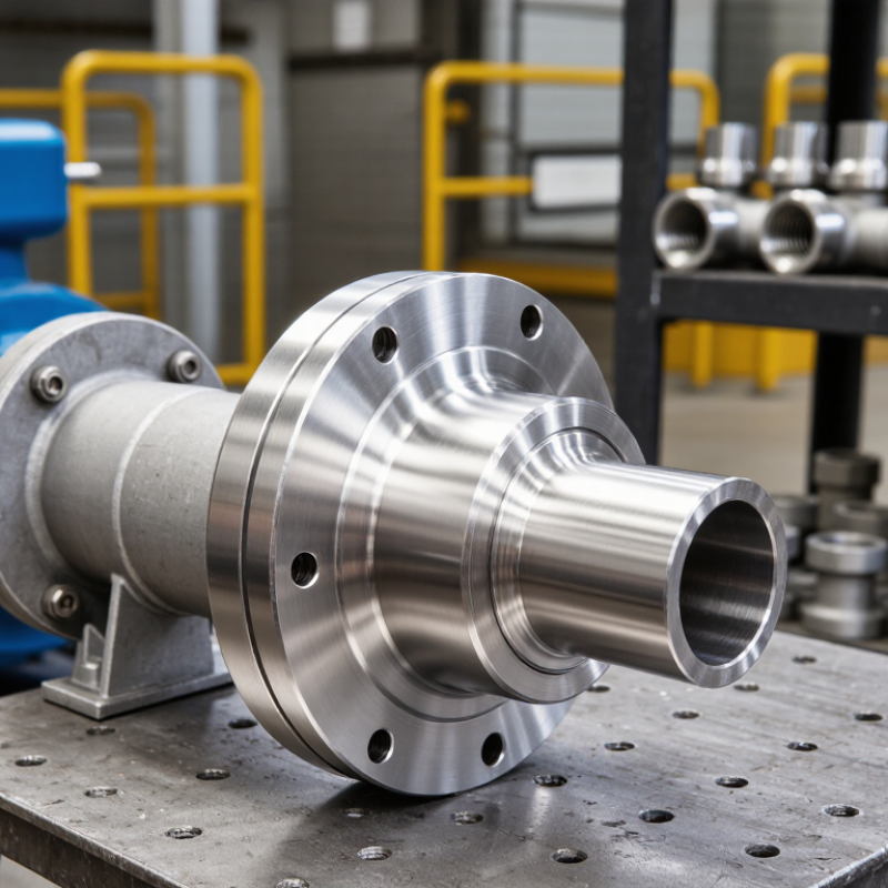
7 Tips for Choosing a Concentric Reducer Fitting
Understand Concentric Reducer Fitting Types and Their Applications
A concentric reducer connects larger and smaller pipes along one central axis. It creates a symmetrical transition for fluids, gases, and process media. This design suits vertical piping, pump discharge lines, and systems where balanced flow matters. It is less suitable near pump suction, where uneven flow can increase turbulence. Fit matters.
Check the reducer type, pipe diameter, wall thickness, and end connection before ordering. Welded, threaded, and grooved versions serve different installation conditions. Stainless steel can resist corrosion, while carbon steel often suits general industrial service. Plastic options may work for lighter chemical or water systems. Do not guess.
Confirm pressure, temperature, flow direction, and media compatibility against the applicable piping code. A reducer with the correct nominal size may still have an unsuitable schedule. Inspect the bore and weld area for dents, cracks, or sharp internal edges. Keep the fitting aligned during installation to reduce stress on nearby valves and supports. Measure twice.
In field work, I have seen drawings omit insulation thickness or maintenance clearance. That small oversight caused rework around a pump connection. Leave space for tools and future inspection. Also verify whether the application needs a concentric or eccentric reducer. Concentric fittings are practical for vertical runs, but eccentric fittings often protect horizontal pump suction from air pockets. Review the actual layout, not only the parts list.
| No. | Selection Dimension | What to Check | Typical Options or Technical Facts | Suitable Applications | Practical Selection Tip |
|---|---|---|---|---|---|
| 1 | Reducer Type | Confirm whether the piping layout requires a concentric or eccentric reducer. | Concentric reducer: The smaller and larger pipe ends share the same centerline. Eccentric reducer: The centerlines are offset. | Concentric reducers are commonly used in vertical pipe runs, general process piping, and applications where a symmetrical flow path is acceptable. | Choose a concentric reducer when maintaining a common pipe centerline is more important than preventing a low-point pocket or preserving a flat pipe elevation. |
| 2 | Nominal Size and Schedule | Match the large-end size, small-end size, wall thickness, and pressure class to the connected pipe. | Reducers are specified by larger nominal pipe size × smaller nominal pipe size. Wall thickness must be compatible with the pipe schedule or selected pressure rating. | Water, steam, compressed air, chemical, oil, gas, and general industrial piping systems. | Verify the applicable dimensional standard and ensure that the fitting bore and wall thickness do not create an unintended restriction or mismatch. |
| 3 | Connection Method | Select the end connection according to the joining method, installation space, and maintenance requirements. | Common configurations include butt-weld ends, socket-weld ends, threaded ends, flanged ends, and grooved ends. The connection type determines installation procedure and inspection requirements. | Butt-weld reducers suit permanent process piping; flanged reducers support dismantling; threaded or socket-weld types suit smaller pipe systems; grooved types support faster mechanical installation. | Make sure the reducer end preparation, flange facing, thread form, or groove dimensions match the mating components exactly. |
| 4 | Material Compatibility | Compare the fitting material with the fluid, operating temperature, pressure, and surrounding environment. | Common material families include carbon steel, stainless steel, alloy steel, ductile iron, and selected plastic materials. Corrosion resistance and temperature capability vary by grade. | Stainless steel is often selected for corrosive or hygienic service; carbon steel is widely used for general industrial service; alloy materials are used for elevated-temperature or specialized duties. | Check chemical compatibility, galvanic-corrosion risk, weldability, temperature limits, and any required lining or coating before purchase. |
| 5 | Flow and Pressure Requirements | Evaluate pressure rating, flow velocity, pressure drop, and the effect of diameter reduction on the system. | A smaller outlet increases flow velocity when the volumetric flow rate remains constant. The reducer should be selected using the applicable piping code, design pressure, and temperature conditions. | Pump discharge lines, process transfer lines, utility piping, and systems that transition between different pipe diameters. | Use a gradual, correctly sized transition and confirm that the reducer will not cause excessive turbulence, vibration, noise, or unacceptable pressure loss. |
| 6 | Installation Orientation | Review the reducer position, pipe slope, drainage needs, venting, and the possibility of liquid or gas accumulation. | A concentric reducer maintains a centered transition but does not provide the same flat-side alignment as an eccentric reducer. | Vertical liquid or gas lines, centered equipment nozzles, compact layouts, and systems where a symmetrical transition is preferred. | Before selecting a concentric type, check whether the line requires self-draining, avoidance of vapor pockets, or prevention of liquid accumulation; an eccentric reducer may be more appropriate in those cases. |
| 7 | Standards, Quality, and Inspection | Confirm dimensional standards, material certification, manufacturing method, inspection level, and required documentation. | Relevant requirements may include ASME, ASTM, EN, ISO, or project-specific specifications. Inspection can include visual examination, dimensional checks, material verification, and non-destructive testing when required. | Critical process lines, pressure systems, power facilities, chemical plants, water infrastructure, and regulated installations. | Request traceable material documentation and verify marking, dimensions, wall thickness, weld quality, and pressure-test requirements before installation. |
© Shipham Valves 2025. All Rights Reserved.
Website By PS Website Design Ltd
Request a Quote/Further Information
Download