What Is an Amorphous Transformer Body Assembly Worktable?

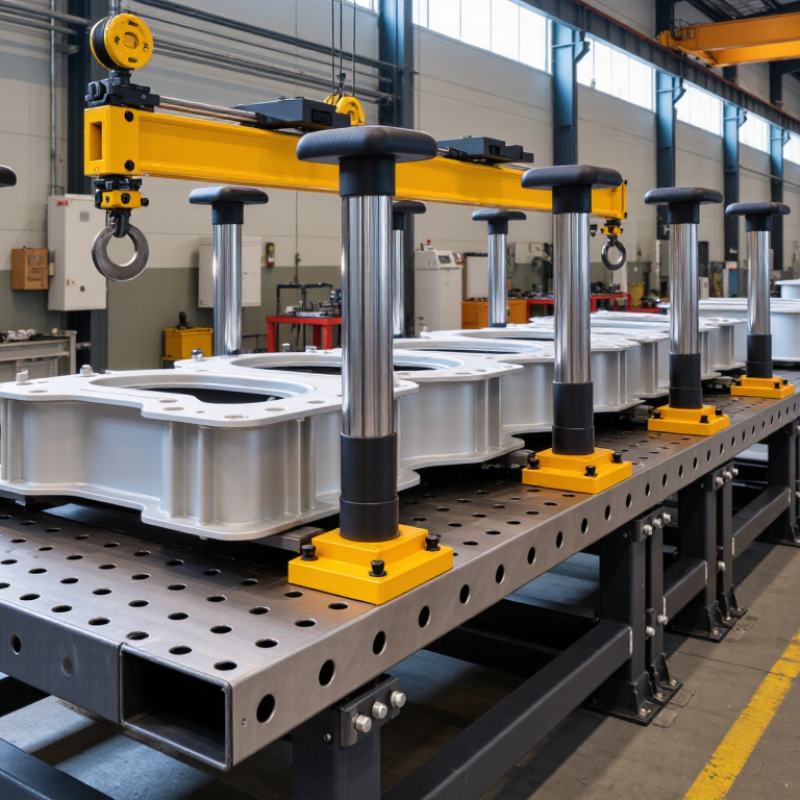
An Amorphous Transformer Body Assembly Worktable is a dedicated station for positioning and supporting transformer components during body assembly. It may include a rigid frame, adjustable supports, clamping points, and clear access for lifting equipment. The exact layout depends on the transformer design and factory process. In practical terms, it helps keep the core and related parts stable while technicians fit, align, and inspect them. Small alignment errors matter.

Amorphous-metal cores are used in some distribution transformers because they can reduce no-load losses compared with conventional core materials. The U.S. Department of Energy’s 2024 distribution-transformer efficiency standards reflect the continuing importance of energy performance in transformer design. The International Energy Agency’s Electricity Grids and Secure Energy Transitions report (2023) says annual grid investment must rise above $600 billion by 2030 to meet stated grid needs. That figure is not a transformer-sales forecast, but it shows the scale of wider network investment.

A well-designed worktable supports repeatable assembly, safer handling, and accessible quality checks. For example, workers should be able to verify clearances, inspect clamped areas, and reach fastening points without awkward repositioning. The table itself does not improve core efficiency; material choice, design, and manufacturing quality do that. Still, the fixture can help prevent avoidable handling damage and alignment problems. No worktable fits every factory. Its useful features should follow the component dimensions, lifting method, and inspection steps actually used on the production floor. Planning can be imperfect at first, so feedback from technicians matters.
What Is an Amorphous Transformer Body Assembly Worktable?

Definition and Purpose of an Amorphous Transformer Body Assembly Worktable

An amorphous transformer body assembly worktable is a stable, purpose-built platform for positioning and assembling a transformer’s core, coils, supports, and body components. Its purpose is practical: keep parts aligned, accessible, and secure while technicians fit and check them. Depending on the design, the table may include adjustable stops, clamping points, lifting access, and a level surface. These features help reduce unwanted movement during assembly. The exact setup varies by transformer size and production process.

Alignment matters here. Technicians can use the worktable to check clearances, fastener access, and the position of insulation before the assembly moves onward. A small offset can complicate later fitting, so measuring points and repeatable locating features are useful. The International Energy Agency’s 2023 report, Electricity Grids and Secure Energy Transitions, says annual grid investment needs to rise from about USD 300 billion today to more than USD 600 billion by 2030. That forecast underscores the need for dependable grid equipment, though it does not measure worktable performance. A table alone cannot guarantee quality. Poor clamping or rushed checks can still introduce errors. Small details matter. The setup should suit the specific assembly, load, and handling method.

Main Components and Worktable Layout

An amorphous transformer body assembly worktable is a stable station for positioning the core, coils, and structural parts during assembly. Its layout should follow the work sequence: core support, coil placement, alignment, clamping, and inspection. A broad, level surface helps prevent the thin amorphous-metal core from twisting or taking uneven pressure. Adjustable stops and padded contact points can hold parts without scraping their edges.

Key components include a rigid frame, a height-adjustable assembly fixture, alignment guides, clamps, and a lifting aid for heavier assemblies. Keep hand tools and measuring equipment within reach, but outside the path used to move the core. The U.S. Department of Energy’s 2013 distribution-transformer rulemaking analysis notes that amorphous cores can reduce no-load losses by roughly 60% compared with conventional electrical steel. That performance makes careful core handling especially relevant. Small misalignments matter.

A practical layout leaves clear access on at least two sides, with marked locations for fasteners and inspection gauges. Operators should be able to check coil-to-core spacing without leaning across the assembly. A low-friction surface may help positioning, but it can also let components drift; test the fixture with the actual assembly weight. A neat bench is not automatically a good one. I would review the layout after a production run, because awkward hand turns are easy to miss on a drawing.

What Is an Amorphous Transformer Body Assembly Worktable? - Main Components and Worktable Layout

An amorphous transformer body assembly worktable is a purpose-arranged workstation for positioning and assembling the core, windings, insulation, and supporting parts of a transformer. The layout below is typical; fixtures and table dimensions should be selected for the transformer design, core geometry, and handling method.

Worktable Zone Main Components Position and Function Layout and Handling Considerations
1. Main support area Rigid frame, level work surface, replaceable protective pads Provides a stable base for assembly and supports the transformer body during fitting and inspection. Keep the surface level and clean. Use smooth, non-abrasive contact surfaces to help protect the thin amorphous core material from scratches and localized impact.
2. Core positioning area Core support blocks, locating stops, adjustable guides, padded clamps Holds the core in its intended position while the body is assembled. Arrange supports to suit the core shape and approved assembly method. Apply only the restraint needed to prevent movement; avoid concentrated pressure that could deform or damage the core.
3. Winding and coil area Coil supports, centering guides, insulated separators Supports and aligns windings as they are fitted around or alongside the core, according to the transformer design. Provide clear access for careful placement. Keep winding edges and leads clear of sharp corners, and use separators where required by the design and insulation system.
4. Insulation and small-parts area Organized trays, insulation-sheet holders, fastener bins, component labels Stores insulation materials and assembly hardware close to the point of use. Separate parts by type and assembly step. Protect insulation from moisture, dust, oil, and accidental creasing; keep loose hardware away from the core and windings.
5. Handling and lifting area Clear lifting access, rated hoist or lifting aid where needed, designated staging space Allows heavy or awkward components to be moved into position without relying on uncontrolled manual handling. Plan the lifting path before assembly. Use lifting equipment and attachments rated for the load, and keep the operator’s view and access to the work area unobstructed.
6. Tools and fastening area Tool holders, torque-controlled tools where specified, fastener bins Keeps assembly tools accessible for joining structural parts and completing specified mechanical connections. Store tools in assigned locations and follow the assembly drawing or work instruction for fastening sequence and torque. Do not place tools on exposed core or winding surfaces.
7. Inspection and electrical-test area Inspection access, measurement tools, test-point access as specified Supports checks of alignment, clearances, connections, and other requirements in the production documentation. Keep inspection points visible and accessible. Electrical tests should be performed only with the specified equipment and safety procedures, by qualified personnel.
8. Operator and material-flow area Operator access, incoming-part staging, completed-assembly staging Organizes the sequence from prepared parts to assembled transformer body and reduces unnecessary handling. Place frequently used parts within comfortable reach while preserving a clear walkway. Keep incoming and completed items separated to reduce mix-ups and prevent accidental contact damage.

Materials and Tools Used During Assembly

An amorphous transformer body assembly worktable supports careful fitting of the core, coil, insulation, and enclosure. Its top should be level, rigid, and broad enough to hold the assembly without forcing parts against an edge. A clean, non-shedding mat helps protect the thin amorphous-metal core from scratches and loose debris. Keep steel filings away. They can cling to magnetic components and complicate cleaning.

Common tools include torque-controlled drivers, soft-jaw clamps, calipers, insulated hand tools, and lifting fixtures matched to the assembly’s weight. Use clamps gently; excessive pressure can distort delicate core sections. Calipers help check clearances around the coil and insulation, while a torque tool makes fastener tightening more repeatable. Operators may also use labeled trays for bolts, spacers, and washers, plus task lighting to inspect narrow gaps. Small parts wander.

Materials vary by transformer design, but may include core bands, coil supports, insulating sheets, fasteners, and protective covers. Confirm each item against the current assembly drawing before work begins. That sounds obvious, yet mixed spacer thicknesses can be hard to spot under poor lighting. The table is a working surface, not a substitute for approved lifting methods or electrical isolation procedures. Review the setup when a new model arrives; old tool layouts do not always fit.

Step-by-Step Transformer Body Assembly Process

What Is an Amorphous Transformer Body Assembly Worktable?

Step-by-Step Transformer Body Assembly Process

An amorphous transformer body assembly worktable is a stable, organized station for assembling the core, coils, insulation, and supporting parts. Its clean, level surface helps protect the thin amorphous metal core from bumps and twisting. Keep drawings, approved tools, and component trays within reach. Small details matter here.

Begin by checking the work order, parts, and core condition against the assembly drawing. Place the core gently in its fixture, then position the coils and insulation in the specified order. Avoid forcing parts into place; resistance can signal misalignment or an incorrect component. Fit brackets and clamps evenly, following the required sequence and torque values. Connect leads only after confirming their labels and routing. Before the body leaves the table, inspect clearances, insulation placement, fasteners, and visible core damage. Record checks as required by the work instructions. Assembly methods vary by transformer design, so the approved drawing and procedures take priority.

Tips: Keep the surface free of loose metal pieces and abrasive debris. Use padded supports where specified. Pause if alignment looks wrong. A rushed adjustment can leave a small problem hidden beneath the next layer. After each major stage, take a moment to compare the assembly with the drawing.

Safety, Precision, and Quality Control Considerations

An amorphous transformer body assembly worktable supports the careful positioning of the core, windings, and enclosure during assembly. Its safety features should be practical, not decorative. A stable frame, rounded edges, clear walkways, and well-placed tool holders reduce avoidable strain and snag risks. Heavy parts may need a lift or adjustable support. Hands should never steady a suspended load. That matters.

Precision starts with repeatable locating points. Adjustable stops and non-marring contact surfaces help keep components aligned without scratching thin laminations or insulation. Operators should see joint areas and reach fasteners without twisting their wrists. Good lighting matters; a small shadow can hide a gap or trapped lead. Still, fixtures can shift with wear, so alignment checks belong in routine setup, not just initial installation.

Quality control works best when checks are built into the work sequence. A checklist can record dimensions, fastener condition, lead routing, and visual defects at defined stages. Use calibrated measuring tools where tolerances require them, and keep rejected parts separate. Cleanliness counts: metal chips or loose hardware near the core can cause problems later. A tidy bench does not guarantee a correct assembly, so independent inspection remains valuable. When a fit feels uncertain, pausing to recheck is better than forcing it.

Amorphous Transformer Body Assembly Worktable: Safety, Precision & Quality

A worktable for assembling amorphous transformer bodies should support safe handling, repeatable positioning, and inspection. These machinery-safety standards provide relevant design and control frameworks.

The bars show standard publication years—not worktable performance scores. ISO 12100 covers machinery risk assessment and risk reduction; IEC 60204-1 addresses electrical equipment of machines; ISO 13849-1 addresses safety-related parts of control systems. Verify applicable editions and local requirements during project design.

Request a Quote/Further Information

    Download